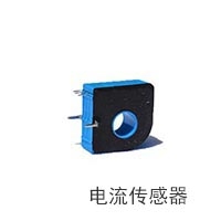
Interpretation of Technical Indicators of Current SensorsIssuing time:2022-11-15 11:24 There are various technical specifications and terms for curre🐻nt sensors. Have you understood them? Below we will provide you with a detailed explanation one by one. 1. Rated current: The effective value of a large current continuously flowing through the sensor under certain conditions. The various model names of current sensors are defined based on the DC peak size. DC current: effective value=peak;🥃 AC c❀urrent: effective value=peak/1.414. 2. Sensor bandwidth: The output capacity of the measured curren🌱t at different frequencies on the secondary side of the sensor. The frequency of 3dB broadband refers to the frequency at which the amplitude of the output signal decays to 0.707 of the input signal amplitude. 3dB=20log (measured value/standard value) 3. Zero drift: The default i💞nitial value of the se🧸nsor every time it is powered on. 4. Temperature drift: The amount of change caused by each degree of temperature change during normal operati🔯on of🌠 a sensor. 5. Time drift: The amount of change in the output of a sensor 🍨caused by changes in usage time. 6. Accuracy: Large error 🃏๊when measuring rated current. 7. Working voltage: The voltagꦫe required for the current sensor to opera🦹te
Measure the DC accuracy of current from 1500A to🧔 10A, and analyze the AC accuracy of current from 1060A to 10A. 1. Test environment construction: (1) Place the IIT1500 current sensor under test and wind the current wire flowing through IIT1500 for 20 turns. The transformation ratio of the tested sensor IIT1500 is 1000:1. Therefore, when the current line flows through a 5A current, due to winding 20 turns, the🐟 equivalent measured current of the tested IIT1500 is 100A, and the secondary output current 🍷of the sensor is 0.1A. (2) Place the standard sensor AIT1000SG current sensor and wind the current wire flowing through AIT1000SG for 10 turns. The conversion ratio of th⭕e standard sensor AIT1000SG is 1500:1. Therefore, when the current line flows through a 5A current, due to winding 10 turns, the equivalent measured current of the standard current sensor AIT1000SG is 50A. At this time, the secondary output current of the sensor is 0.0333A. (3) Use the DC power source ITN6512D to output DC current. The positive output current of the current source flows through the tested current sensor IIT1500 (with 20 turns of currentꦦ wire winding), and then the test wire is led out and flows through the🅠 standard current sensor AIT1000SG (with 10 turns of current wire winding), and then returns to the negative electrode of the DC power source ITN6512D. Therefore, when the power source outputs current, the voltage values output from the secondary side of the standard sensor and the measured sensor should theoretically be consistent. (4) Use the AC power source HZ601 to output AC current. The positive output current of the current source flows through the tested current sensor IIT1500 (with a current wire wrapped for 20 turns), and then the test wire is led out to flow through the standard current sensor AIT1000SG (with a c🐠urrent wire wrapped for 10 turns), before returning to the neꦑgative electrode of the AC power source HZ601. Therefore, when the power source outputs current, the voltage values output from the secondary side of the standard sensor and the measured sensor should theoretically be consistent. (5) Weld the output end of the standard current sensor with a 3-ohm resistor (accuracy 0.1%, temperature drift ± 5ppm), convert the output current of the current sensor into an output voltage, weld the output end of the measured current sensor with a 1-ohm resistor (accuracy 0.1%, temperature drift ± 5ppm), and convert the output current of the current sensor into an output voltage for comparison. Connect the output voltage of the measured sensor to the front end of FLUKE8558A voltage measurement, and connect the output voltage of the standard sensor to the back end of FLUKE8558A voltage measuremen♐t. Compare the error through the ratio measurement function of the e🌜ight and a half digit multimeter FLUKE8558A. 2. Test steps and methods: (1) Set the ratio measur꧋ement on the eight and a half digit multimeter FLUKE8558A, set the resolution to 8 digits, set the voltage gear to automatic gear, and pr🅷ess the Input key to set the ratio measurement method for the front-end input voltage and back-end input voltage. (2) Control the DC power source to output different measured current values. After the current source stabilizes, use an eight and a half digit multimeter FLUKE8558A to measure the♋ ratio between the output voltage of the measured sensor and the output voltage of the standard current sensor, and record it. |


